Monday, January 26, 2015

Full duplex Intercom

This design allows to operate two intercom stations leaving the operator free of using his/her hands in some other occupation, thus avoiding the usual "push-to-talk" operation mode.

No complex changeover switching is required: the two units are connected together by means of a thin screened cable. As both microphones and loudspeakers are always in operation, a special circuit is used to avoid that the loudspeaker output can be picked-up by the microphone enclosed in the same box, causing a very undesirable and loud "howl", i.e. the well known "Larsen effect". A "Private" switch allows microphone muting, if required.
Full-duplex Intercom Circuit Diagram :
 
Parts:
P1_____________22K Log. Potentiometer
R1_____________22K 1/4W Resistor
R2,R3_________100K 1/4W Resistors
R4_____________47K 1/4W Resistor
R5______________2K2 1/4W Resistor (See Notes)
R6______________6K8 1/4W Resistor
R7_____________22K 1/2W Carbon or Cermet Trimmer
R8______________2K7 1/4W Resistor
C1,C6_________100nF 63V Polyester or Ceramic Capacitors
C2,C3__________10µF 63V Electrolytic Capacitors
C4_____________22µF 25V Electrolytic Capacitor
C5_____________22nF 63V Polyester or Ceramic Capacitor
C7____________470µF 25V Electrolytic Capacitor
Q1____________BC547 45V 100mA NPN Transistor
IC1_________TDA7052 Audio power amplifier IC
SW1____________SPST miniature Switch
MIC____________Miniature electret microphone
SPKR___________8 Ohm Loudspeaker
Screened cable (See Text)
Circuit operation:
The circuit uses the TDA7052 audio power amplifier IC, capable of delivering about 1 Watt of output power at a supply voltage comprised in the 6 - 12V range. The unusual feature of this design is the microphone amplifier Q1: its 180° phase-shifted audio output taken at the Collector and its in-phase output taken at the Emitter are mixed by the C3, C4, R7 and R8 network and R7 is trimmed until the two incoming signals almost cancel out. In this way, the loudspeaker will reproduce a very faint copy of the signals picked-up by the microphone.
At the same time, as both Collectors of the two intercom units are tied together, the 180° phase-shifted signal will pass to the audio amplifier of the second unit without attenuation, so it will be loudly reproduced by its loudspeaker. The same operation will occur when speaking into the microphone of the second unit: if R7 will be correctly set, almost no output will be heard from its loudspeaker but a loud and clear reproduction will be heard at the first unit output.
Notes:
  • The circuit is shown already doubled in the diagram. The two units can be built into two separate boxes and connected by a thin screened cable having the length desired.
  • The cable screen is the negative ground path and the central wire is the signal path.
  • The power supply can be a common wall-plug adapter having a voltage output in the 6 - 12V dc range @ about 200mA.
  • Enclosing the power supply in the box of one unit, the other unit can be easily fed by using a two-wire screened cable, its second wire becoming the positive dc path.
  • To avoid a two-wire screened cable, each unit may have its own separate power supply.
  • Please note that R5 is the only part of the circuit that must not be doubled.
  • Closing SW1 prevents signal transmission only, not reception.
  • To setup the circuit, rotate the volume control (P1) of the first unit near its maximum and speak into the microphone. Adjust Trimmer R7 until your voice becomes almost inaudible when reproduced by the loudspeaker of the same unit.
  • Do the same as above with the second unit.

Thursday, November 20, 2014

8 Relay Control Circuit

8 Relay Control Circuit
R1-8=4.7 Kohms T1-8= BD139 (R1-8=15 Kohms if T1-8=BD679)
RL1-8=6V-24V dc Relay D1-8=1N4148
8 

Crystal Radio Audio Amplifier Circuit

CrystalCrystal Radio Audio Amplifier Circuit

Here is a simple audio amplifier application a TL431 blow regulator. The amplifier will accommodate room-filling aggregate from an accustomed clear radio outfitted with a long-wire antenna and acceptable ground. The chip is agnate in complication to a simple one-transistor radio but the achievement is far superior.

The TL431 is accessible in a TO-92 amalgamation and it looks like an accustomed transistor so your hobbyist accompany will be afflicted by the aggregate you are accepting with alone one transistor! The amplifier may be acclimated for added projects, too. Higher impedance headphones and speakers may additionally be used. An earphone from an old blast will accord boisterous aggregate and abundant sensitivity! The 68 ohm resistor may be added to several hundred ohms back application aerial impedance earphones to save array power.

Wednesday, November 19, 2014

Toggle Switch with IR

Toggle switch in this article is a series of toggle switches that are controlled by infrared light. The series toggle switch is made from a combination of data flip-flop CD4013 2 units. Receiver circuit of the infrared light signals arranged with infrared receiver as found on television remote receiver. Infrared signal from remote is used as clock signals and data to the data flip-flop first. then the second flip-flop data set as a toggle flip-flop toggle the output signal is used to drive the relay. for more details can be seen in thethe following image .


Toggle


Series Toggle Switch With Infra Red (IR) that is required to supply voltage range of 12VDC and the output of Toggle Switch With Infra Red (IR) is dapt used to turn on the lights or other electronic devices with DC or AC voltage source. Series Toggle Switch With Infra Red (IR) was isolated from the load that is placed for use as the final relay.

Variable Speed ​​DC Motor Controller 12V

For more details can be seen from a series of Variable Speed ​​DC Motor Controller 12V follows.

Series Variable Speed ​​DC Motor Controller 12V This is one series that can be used to regulate speed DC12V motor with PWM technique. Series Variable Speed ​​DC Motor Controller 12V uses a 555 timer IC as a PWM pulse generator to regulate the motor speed DC12 Volt. DC motor speed control process performed by adjusting the potentiometer R1 lever which in principle is set High and Low pulse width of the PWM pulse.

Series Variable Speed ​​DC Motor Controller 12V above the power MOSFET drivers in the form of a IRFZ46N is directly associated with DC motors. Working voltage of this circuit can be adjusted according to needs-driven DC motor, this circuit can work from 3-18VDC.

Stereo Power Amplifier STA550

Stereo Power Amplifier 2x70Watt STA550 is chip audio power with BASH concept that can be connected with digital devices. 2x70Watt STA550 Stereo Power Amplifier is an amplifier with BTL system with symmetrical power supply with ground. Power amplifier STA550 uses power output transistor which is on the chip and is set to produce a high efficiency audio power. Power output on the STA550 is using the system without copling ac bridge (direct) and zero offset.

Strengthening of the STA550 from stereo power amplifier is +12 dB. 2x70Watt STA550 Stereo Power Amplifier is equipped with temperature sensors for protection from overheating and current-limiting protection system for power amplifier. 2x70Watt STA550 Stereo Power Amplifier is equipped with standby and mute controls to regulate silent or active mode power amplifier.


    Feature :

  •      Monochip Bridge Stereo Amplifier with Bash ® Architecture
  •      55 +55 w Output Power @ Rl = 4 / 8 W, THD = 0.5%
  •      70 +70 w Output Power @ Rl = 4 / 8 W, THD = 10%
  •      High Dynamic preamplifier Input Stages
  •      Programmable External Feedback Type Compressors
  •      AC Coupled Input Output Bridge To Class Ab Amplifier
  •     Precision Rectifiers To Drive The Digital Converter
  •      Proportional Over Power Output Current Limit To The Digital Converter
  •      Absolute Power Transistor Bridge Output Power Protection
  •      Absolute Output Current Limit
  •      Integrated Thermal Protection
  •      Power Supply Over-Voltage Protection Flexiwatt With 27 Pin Power Package
  •      Bash ® Licence Require

Tuesday, November 18, 2014

10Mhz to 1 MHz Frequency Converter

10Mhz to 1 MHz Frequency Converter Circuit

10Mhz

Part ListIC1 7404 = 1
IC2 7490A = 1
R 1 K = 2
R 3.3 K = 1
C Trim Polymer 39 pF = 1
C Electrophoresis 4.7 uF 16V = 1
C Milar 47 nF 16 V = 1
C Milar 10 nF 16 V = 1
C Ceramic 68 pF 50 V = 1 

Seven Segment 4 Digit

Seven segment 4 Digit display Multiplex in electronic device applications is drain port  a micro controller or data point that will be on display, especially if the data to be displayed more than 1 digit. necessary path to control the resources of each 7 segment and the path to input data on the 7 segment. Circuit 7 Segment 4 Digit Multiplex is a way to save the port or micro controller data path that will be displayed. Series Display 7 Segment 4 Digit Multiplex uses BCD to 7 segment decoder 74LS247 BCD to encode data from the data that will be displayed, then for each resource viewer 7 segment using the set of transistors as electronic switches. Current flowing in the viewer in a series of 7 segment Display 7 Segment 4 Digit Multiplex is in limiting use yag resistor in series pairs in each collector transistor.


Resistors are mounted in series of LED is used as a barrier for current flow that flows through the LED does not exceed the maximum allowable, current that is equal to 20 mA.

Make 5 1 Channel Audio Amplifier

5.1 channel amplifier consists of 6 amplifiers 1 channel mono, which has certain specifications on each canals. Has 6 channel surround sound amplifier that consists of Front Left ,Center,Front Right ,Rear Left (Left Surround),Rear Right (Right Surround) , and LFE (Subwoofer).For clarity I give a simple illustration of the layout and the circuit for these speakers.

5.1 Speaker Setup

Accoustic Field Generator
Acoustic Field Generator is generating acoustic sound with surround effects are adjustable with a standard Dolby Surround, able to produce surround sound is good enough but not too much need of funds. Technological developments as if not only focused on one area alone but on all fronts. The development of technologies that exist today one of them is in the field of audio. With more advanced audio technology today not only as mere entertainment but has become a hobby, hobby is not cheap of course. Many audio enthusiasts trying to make music sound that sounded to be very hard to make music sound as live, the addition of the amplifier, woofer or special speakers that cost is not cheap.

The sound effects are living seems to now is something that most do not have to exist in every good audio devices. This effect is basically a surround effect that can lead to sound as though coming from different directions and his voice can still be heard clearly. Currently Compo-tape tape that has been a lot of these facilities surround sound but not good enough when heard from a considerable distance because of the effects surroundnya missing. This is because the distance is too far listener and speaker, speaker layout is not quite right, or the effect of unfavorable surround.


Surround effects are nice and can be heard with a good surround system is a system that is in movie theaters and to make it not a bit prangkat needed funds. However, if satisfaction remains the number one then the fund is not a major problem. To find a middle ground between price and quality surround effects it was attempted to make the Acoustic Field Generator that can produce surround sound is good enough but not too much need of funds. Acoustic Field Generator is capable of generating acoustic sound with surround effects are adjustable with a standard Dolby Surround.


Accoustic Field Generator Construction

Basically an Acoustic Field Generator built from op-amp circuit and filters. Op-amps are usually used as a voltage amplifier in the Acoustic Field Generator is more widely used as active filters. The filter in the tool is very instrumental in creating an acoustic sound that is really clear, but in practice, almost all the filters, do not miss the precision of the signal with a specific frequency. An op-amp is good for this application is the op-amp which has a wide bandwidth, rise time, slew rate and fast setting timenya. In addition to op-amp and active filter, theres more important parts of the power supply. This is the part that is instrumental in creating excellence acoustic sound because of the bad power supply which is the only producer of noise, which will enter into a voice signal path so that should clear acoustic sound into an acoustic sound with the addition of reverberation (noise). The power supply used is the twin power supply + / - 18 volts DC. Part Acoustic Field Generators


Before we start doing this project, it helps us know in advance about the function of each speaker.


Front Channel

Channel Front is a forward channel input signal LR. LR signal is passed to an amplifier with gain = 1 so that this signal is passed without change / to filter the input signal LR. Front Left and Front Right, is a public speaker that we encountered in stereo amplifier, consisting of a woofer and tweeter. Woofers generally produce low tone sound with a frequency range ranging from 80Hz - 250Hz, while the tweeter produces a high tone with a frequency range between 15kHz - 20kHz. For projects that we will create, its good we use a good quality woofer, with a size of 10 inches and a type piezoelectric tweeter for each speaker fronts.


Front Channel 5.1 Amplifier


Center Channel

Center, the fullrange speakers, which produce sound with a frequency range between 80Hz - 10Khz. Output from the center speaker is a summation of left and right signal (left + right = center). In a movie or song Dolby Surround format, commonly used center for dialogue / vocal or speech of the actor / artist of a film and to produce a sound that moves ahead of us.


Center Channel 5.1 Amplifier


Rear Channel with Surround System

In this section is the core of this hard perangakat. These sections produce surround effects. To produce the surround effect is required special IC MN3005 / 8 and MN3101. Both these ICs will delay the incoming signal in several phases, so that the signal output from this phase will be left with a signal phase of the signal lain.Pada this section L and R are deducted (LR) and then passed in the buffer, filter LPF, delay line, filter LPF (7KHz) and the last is a splitter between the signals R and L. Circuit which causes the surround effect is 75KHz LPF circuit that produces its output fed to the Right Rear 75KHz LPF amplifier input while it diparalel with the Left Rear amplifier input so as to produce two signals L and R which is basically a LR signal a phase lag with the original signal phase.


Rear Left and Rear Right, also known as surround speakers. This speaker is generally a semi-midrange speaker (usually used on television or Mini Compo), commonly called satellite speakers. In a movie surround speakers are used to generate the audible sound of distant voices or sounds that move from the back of our approach. In a music surround speakers produce sound backing vocals and generally sounds like guitars, violins and trumpets sounded clear here.
Rear Channel 5.1 Amplifier


Subwoofer Channel

Part of this subwoofer is the summation of inputs L and R inputs to a summing amplifier. The output of the summing amplifier is passed to a class 2A LPF which will only pass signals with frequency rendah.Subwoofer, sometimes referred to as LFE (Low Frequency Effect). For these speakers using a subwoofer speaker. Speaker woofer speaker subwoofer is designed specifically to be able to respond to sound with a very low frequency, ranging from 15Hz - 120Hz. For low tone effect can be produced by either (without any harmonic frequency), then the acoustic box / box speakers are also designed specifically with a variety of methods (there are no visible speaker / inside the box, there are that use insulation / labyrinth, etc. ), so that the speaker is capable of compressing the air effectively, so that will feel the effect.

Subwoofer Channel 5.1 Amplifier


Wiring Diagram Home Theater Amplifier / 5.1 Amplifier


Monday, November 17, 2014

Make A Virtual Phone Battery

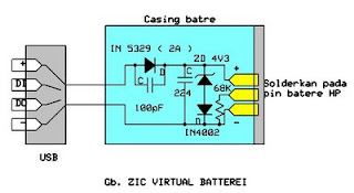
Virtual cell phone battery is a replacement cell phone batteries for those of you who use the phone as a modem. Including myself, who use the phone as a modem HAIER d1200p internet.  Why must use this virtual battery. For those who surf hobby "full time" with a phone modem, would know the problem, the battery gets hot and fast reply wasteful even worn out.
virtual
This tool is a good solution to keep and care for our cell phones from the possibility of damage from over-charging its battery.I created a virtual battery works as follows:We take the source of its power supply from the USB port because the port is very easy and simple to use and simply provide a standard current source when the phone is online (500-750mA).

The workings of the circuit is as follows:Diodes or diode 2Amper in 5239 this standard to provide a useful addition to the polarity of the voltage which is also a component of protection against misuse. You can just use a 1 Amp diode (IN4002-4007). I use the IN 5239 is due to be durable, more resistant to heat.4v3 zener diode IN4007 and configured to create a portal voltage of 5V (4.3 + 0.7 volt zener Vin4007) and is useful as a protection system against possible voltage spikes in the event of damage to the CPU.220nF capacitor as a stabilizer and a substitute for the original battery cells.

The following also 100pF capacitor to smooth and filter the dc current through the diode 5239 which came out of the induction logging.Configuration between zener4v3, IN4007 diode and C 220n form a cell replacement from the actual battery cells, because the battery was actually a capacitor which had a large capacity.You can just remove the three components mentioned above. although it can work fine .

But results are not as good as that use virtual cell (replacement), which certainly was the security which we have to think to avoid the things which are not in want.Making way is to use an old cell phone batteries which have been wasting his cell, a raft of this circuit and the solder terminals on the batteries with the polarity distinguished. Make two holes for the cable to the jack / USB jack.

 Determine the length of cable required to taste and use stranded cable with a diameter of at least 1mm.If some type of cell phone batteries are very thin, use a small box for this circuit and connect the two wires to the output voltage again for hp battery casing. Or also if you do not have a former battery casing, use alligator clips to the battery terminal on the phone .. Pin the middle of the virtual pin replacement battery is BSI (Battery Size Insdicator) is useful for HP Nokia.

Rain Detector Using 555

Rain Detector Using 555 is a simple alarm that can be used to find out it was raining. In principle, Rain Detector Using 555 is an astable multivibrator which is prepared by IC555 with installed a sensor that can detect water. Astable multivibrator with the 555 is set in the audio frequency with a frequency of 1 KHz. The series of Using Rain Detector 555 can be disupplay with a voltage source that is free enough from 5-15 VDC. In the application circuit Rain Detector Using this 555 can be mounted motor, car or other object that we want to protect from rain.

Water sensors that are used in circuit 555 Rain Detector Using this we can make yourself degan a PCB that we make the path as shown in the image above or as disclosed from the image above is by using aluminum foil taped to a board or boards that are plastic insulator . The important principle of the sensor is to conduct electrical current very well when the surface is exposed to water even a little. Hopefully useful ...

Class A MOSFET Amplifier 2SK1058


This is simple class A MOSFET amplifier 2SK1058 used in the circuit. It is easy to do, you should use a 24V supply volt at high current. using amplifier with Class A tube preamp based on 12AU7. It produces the purest sound. I have no idea of ​​the levels of distortion, but has a very fine and delicate texture quality. With only one watt speaker output should be used efficiently. Lower is better than expected and the stage design of the units of my 12 "base 63L 3-way speakers with ease.

Sunday, November 16, 2014

Type of UPS Uninterruptible Power Supply

UPS design of the model is divided into several types that produce different performance characteristics:
A. Standby
2. Line Interactive
3. Double Conversion On-Line
4. Delta Conversion On-Line
Standby UPS types
This type is commonly used by home users for the Presidency with their PC. UPS to be able to do this type of filtration against power failures and flow management, in addition to design efficient, small size and inexpensive.

Line Interactive UPS types
UPS is the type most often used in small business unit, web developer, and a number of servers located in government departments. Because, in addition to having high levels of reliability, this type also have the ability to adjust the voltage that is sufficient
fine.
UPS has an inverter is always connected to the output of the UPS system to convert the power from batteries into AC. In normal circumstances, the Inverter will perform battery charging. While in a state of power outages, Transfer Switch will close and drain power from the batteries to the UPS output. Position that is always connected to the inverter output filter provides additional power. This makes the type of UPS is widely used for server and electrical conditions are not too good.

Double Conversion type UPS On-Line
This type is most common for UPS with power more than 10kVA. These types have in common with the type of Standby. Only this type has a power source located on the inverter, not the AC power source. In this type, the main electricity supply interruption will not trigger a transfer switch for the incoming AC power to the central input to charge the batteries that provide power to the Inverter located at the output. Therefore, when the AC power is disconnected, the flow of energy will be transferred immediately without taking a break when the transfer occurs. This type of UPS above shows the performance of the average. Can be said of this type of approach the ideal of a UPS, unfortunately this type of heat is high enough.

UPS type Delta Conversion On-Line
Almost the same as the Double Conversion type, type Delta used to always supply voltage Inverter. When the power supply is interrupted, this type do the same with Double Conversion type. Delta Conversion has two functions, the first is to control the input power characteristics. While the second function is to control the input current to direct the process of charging the battery system. The thing to remember is to minimize this type of energy is wasted. In addition, it has a high compatibility to various types of generators and reduce the need for the use of cables.

Saturday, November 15, 2014

MUSICAL BELL CIRCUIT

This circuits uses very few component and gives melody sound. It uses 3 terminal IC UM66 and can be build small enough to be placed inside a greeting card and operated off a single 3V flat button cell.There is not much to the circuit. The UM66 is connected to its supply and its output fed to a transistor for amplification. Any common speaker can be used or a “flat” piezoelectric tweeter like the one found in alarm wrist watches. If you use the piezo, then it can be connected directly between the output pin 1 and ground pin 3 without the transistor.

The UM66 looks like a transistor with 3 terminals. It is complete miniature tone generator with a tune. Now they come with wide variety of different tunes.

For amplification we have used a NPN transistor which is BC548. Here BC548 makes a common emitter circuit. For limiting the base current we have used a resistance of 220 Ohms so that transistor will not get damaged by excess current.

Circuit Diagram

Circuit Diagram

Important Points

  • Identify emitter base collector of transistor and pin no. of IC UM66.
  • Make sure all points are well soldered according to the Circuit Diagram and no dry solders. Wrong connection of IC may heat up and get damage.

Friday, November 14, 2014

F M RECIEVER

Communication in F.M. band is easy, less expensive and has many more advantage. As we have already published Simple F.M. transmitter circuit in previous article. Now, here is a circuit diagram with description of Powerful F.M. receiver using single IC used to receive frequency range of 88 MHz to 108 MHz in F.M. band. FM employs frequency modulation scheme. In FM frequency is modulated and amplitude remains constant.

Circuit Description


With the circuit described here (F.M. receiver) one can easily receive F.M. signal and is build around IC TEA5591 (IC1). Transmitted F.M. R.F. signal is received by telescopic antenna and is given to pin 2 of IC1 passes though band pass filter made from coil L2 and capacitor C4. R.F. signal given to IC1 is amplified and is tuned with the help of capacitors C9, C13 and coil L1. Coil L3 with capacitors C8 and C14 is configured as oscillator and its output is given to pin no 22 and 23 of IC1 in order obtain IF frequency by mixing with tuned R.F. frequency. Tuned IF frequency of 10.7 MHz is obtained from amplifier made from coil L4 and capacitors C10 & C11. Ceramic filter XT1 and XT2 is used to filter IF frequency and is given to pin no 4 of IC1. Internal detector stage is used to detect F.M. signal. Finally output from F.M. receiver is obtained from pin 11 and is given to audio amplifier stage.

Circuit Diagram


Parts List

  • Resistor (all ¼-watt, ± 5% Carbon)
  • R1 = 820 Ω
  • Capacitors
  • C1,C2 = 4.7 µF/35V
  • C3,C5 = 470 PF
  • C4 = 22 PF
  • C6 = 0.02 µF
  • C7,C10 = 0.01 µF
  • C8,C9 = 27 PF
  • C11 = 47 KPF
  • C12 = 220 µF/25V
  • VC1 = 22 PF
  • VC2 = 39 PF
  • Semiconductors
  • IC1 = TEA5591
  • D1 = 1N4007
  • Miscellaneous
  • L1, L3 = 3 turns on any pencil ; 21 gauge wire
  • L2 = 5 turns on any pencil ; 21 gauge wire
  • L4 = F.M. I.F.T.
  • XT1,XT2 = 10.7 MHz
  • Antenna

Booster Low Power Voltage Doubler Diagram Circuit

All miniature electronic devices operate off batteries. Some of them need higher than the standard battery voltages to operate efficiently. If the battery of that specific voltage is unavailable, we are forced to connect additional cells in series to step up the DC voltage. Thus, the true meaning of miniaturisation is lost. A simple way to overcome this problem is to employ a voltage doubler, if the device under consideration can operate at a small current.

Here we present a low-power voltage doubler circuit that can be readily used with devices that demand higher voltage than that of a standard battery but low operating current to work with. The circuit is quite simple as it uses only a few components. Yet, the output efficiency is 75 to 85 percent along its operating voltage range. The available battery voltage is almost doubled at the output of the circuit.

Here IC1 is wired as an astable multivibrator to generate rectangular pulses at around 10 kHz. This frequency and duty cycle of the pulses can be varied using preset VR1. The pulses are applied to switching transistors T1 and T2 for driving the output section, which is configured as a voltage-doubling circuit. The doubled voltage is available across capacitor C5. During each cycle of the pulse occurance, the high level drives T1 into its saturation, keeping transistor T2 cut off.Circuit diagram:
Low-Power Voltage Doubler Circuit Diagram

So transistor T1 charges capacitor C4 via the path formed by diodes D2 and D1 to a voltage level slightly lesser than the supply. But during the low period of the pulse, transistor T1 is cut off while transistor T2 is driven into saturation. Now, transistor T2 raises the charge on the negative pole of capacitor C4 by another step equal to the supply voltage. Therefore an equal amount of charging is built up on capacitor C5 via diode D3.

This doubling action increases the total voltage across capacitor C5 to almost double the input voltage. If the output of the pulse generator is maintained with a high enough amplitude and frequency, the output voltage and current remain constant and cater to the needs of the load. Even with the half-wave function, this circuit is almost free of ripple voltage. If the connected load doesn’t require a high current, the efficiency can be expected in the upper 90 percentranges.

Since the input voltage is doubled, the current drain from the input power supply is also doubled at the input but halved at the output. One point of caution is that if the multivibrator’s frequency is fairly high, the output may suffer with the interference imposed over the DC voltage. In this case, the frequency must be set favorably by trials and actual load connection procedure. This tiny circuit can be assembled on the general-purpose PCB. If all of the components are surface-mount type, the whole module can be genuinely miniaturized.EFY Lab note.
During testing with input of 8V and 1.25mA load current the output voltage was found to be around 13V.
Source: EFY Mag

Thursday, November 13, 2014

Alternating on off switch electronic project circuit with explanation


A very simple alternating on off switch electronic circuit project can be designed using an 4096 CMOS hex inverter and some common electronic parts.
IC1is a regular Hex-inverter type and is constructed with MOS P-channel and N-channel enhancement mode devices in a single monolithic structure.
First push from this alternating on off switch activates the relay and another push de-activates the relay.

The type for D1 in not critical, even a 1N4148 will work.
Q1 transistor is an 2N4401 type , but can be replaced with some other type like : N100, NTE123A, 2N3904, 2N2222, 2N4013, etc.
For C2, if you find the relay acts not fast enough, you can change it to a lower value or use a ceramic cap of around 0.1μF.
The circuit can be powered from a 9 or 12 volts DC power supply circuit .

Unused input pins must be connected to an appropriate logic level and unused output pins must be left open.
Relay used in this project is an 6 volts relay type . R4 and LED1 are optional and can be removed from the circuit .

1000 watt power inverter circuit diagram

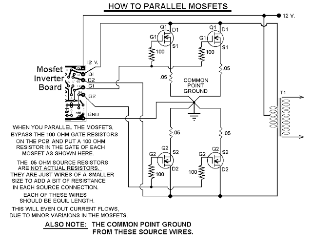
This 1000 watt power inverter circuit diagram based on MOSFET RF50N06.If you want more power then  add additional  MOSFET paralleled at RF50N06.This MOSFETS are  60 Volts and 50 Amps as rated.  It is necessary to connect  a  FUSE with the power line and always a LOAD have to connected while power is being  applied . The output power of this inverter is up-to 1k watt , it depends on output power transformer . You can use your custom transformer with experimenting for best result.

1000w
Fig: 1000 watt power inverter circuit diagram

How to parallel MOSFETs | 1000 watt power inverter


parallel
Fig-2: Parallel MOSFET Power Inverter


Circuit Credit: http://www3.telus.net/chemelec/Projects/Inverter/Mosfet-Inverter.htm

Wednesday, November 12, 2014

Booster for Input Impedance Circuit and explanation

The input impedance of a.c.-coupled op amp circuits depends almost entirely on the resistance that sets the d.c. operating point. If CMOS op amps are used, the input is high, in current op amps up to 10 MΩ. If a higher value is needed, a bootstrap may be used, which enables the input impedance to be boosted artificially to a very high value. In the diagram, resistors R1 plus R2 form the resistance that sets the d.c. operating point for opamp IC1. If no other actions were taken, the input impedance would be about 20 MΩ. However, part of the input signal is fed back in phase, so that the alternating current through R1 is smaller. The input impedance, Zin, is then: Zin=(R2+R3)/R3)(R1+R2). With component values as specified, Zin has a value of about 1GΩ. The circuit draws a current of about 3 mA.Circuit diagram:Input
Input Impedance Booster Circuit Diagram

Oxygen Sensor Simulator

This oxygen Sensor simulator is built from a 555 and few other common parts. Just when I thought Id seen all the uses for the 555. The oxygen sensor on a cars exhaust is used to determine how efficiently the fuel mixture is to an engine.

The oxygen sensor simulator as built on a protoboard. Note the cigarette lighter plug used for power source. The adjustment knob is at the left, and the switch is on the right. The red indicator LED is in the middle. Only use red, because the voltage drop of the LED is part of the circuit!