Showing posts with label battery. Show all posts

Monday, November 17, 2014

Make A Virtual Phone Battery

Virtual cell phone battery is a replacement cell phone batteries for those of you who use the phone as a modem. Including myself, who use the phone as a modem HAIER d1200p internet.  Why must use this virtual battery. For those who surf hobby "full time" with a phone modem, would know the problem, the battery gets hot and fast reply wasteful even worn out.
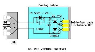
virtual
This tool is a good solution to keep and care for our cell phones from the possibility of damage from over-charging its battery.I created a virtual battery works as follows:We take the source of its power supply from the USB port because the port is very easy and simple to use and simply provide a standard current source when the phone is online (500-750mA).

The workings of the circuit is as follows:Diodes or diode 2Amper in 5239 this standard to provide a useful addition to the polarity of the voltage which is also a component of protection against misuse. You can just use a 1 Amp diode (IN4002-4007). I use the IN 5239 is due to be durable, more resistant to heat.4v3 zener diode IN4007 and configured to create a portal voltage of 5V (4.3 + 0.7 volt zener Vin4007) and is useful as a protection system against possible voltage spikes in the event of damage to the CPU.220nF capacitor as a stabilizer and a substitute for the original battery cells.

The following also 100pF capacitor to smooth and filter the dc current through the diode 5239 which came out of the induction logging.Configuration between zener4v3, IN4007 diode and C 220n form a cell replacement from the actual battery cells, because the battery was actually a capacitor which had a large capacity.You can just remove the three components mentioned above. although it can work fine .

But results are not as good as that use virtual cell (replacement), which certainly was the security which we have to think to avoid the things which are not in want.Making way is to use an old cell phone batteries which have been wasting his cell, a raft of this circuit and the solder terminals on the batteries with the polarity distinguished. Make two holes for the cable to the jack / USB jack.

 Determine the length of cable required to taste and use stranded cable with a diameter of at least 1mm.If some type of cell phone batteries are very thin, use a small box for this circuit and connect the two wires to the output voltage again for hp battery casing. Or also if you do not have a former battery casing, use alligator clips to the battery terminal on the phone .. Pin the middle of the virtual pin replacement battery is BSI (Battery Size Insdicator) is useful for HP Nokia.

Thursday, November 6, 2014

9V Automatic Battery NiCd Charger

This automatic NiCd charger for 9V NiCd batteries is using 555 timer properties and is very easy to build. Why is an automatic 9 volts NiCd battery charger? Because you can leave the battery for charging as much as you like: it will be always completely charged and ready for use when is needed. It wont be overcharged and it will not discharge.

9V Automatic Battery NiCd Charger Circuit Diagram :

charger-circuit-diagram

With the values presented in the circuit diagram, the battery charger NiCd circuit is suitable for 6V and 9V batteries. 9 volt types with 6 and 7 cells are charging with 20mA; P1 must be adjusted so that the NiCd charger disconnects after 14 hours. Window inferior level is set at 1V below this value with P2. 5V battery type with 4 or 5 cells are charged at 55mA. Again, with P1 adjust the NiCd charger circuit so it disconnects after 14 hours. Window inferior level must be set at 0.8V below this value.


Monday, September 8, 2014

Under voltage Indicator for Battery Equipment Wiring diagram Schematic

This is the simple Under voltage Indicator for Battery Equipment Circuit Diagram. Due to the low duty cycle of flashing LED, the average current drain is 1 mA or less. The NE555 will trigger the LED on when the monitored voltage falls to 12 volts.The ratio of Rl to R2 only needs to he changed if it is desired to change the voltage point at which the LED is triggered.


Under voltage Indicator for Battery Equipment Circuit Diagram


Under

Friday, September 5, 2014

Capacitance Operated Battery Powered Light Wiring diagram Schematic

Build a simple Capacitance Operated Battery Powered Light Circuit Diagram. Capacitance is the ability of a body to store an electrical charge. Any object that can be electrically charged exhibits capacitance. A common form of energy storage device is a parallel-plate capacitor. Touch the plate and the light will go on and constant of the 47 µf capacitor and the 2M remain on for a time determined by the time resistor.

Capacitance Operated Battery Powered Light Circuit Diagram

Capacitance

Wednesday, August 27, 2014

Solar battery charger


This is solar battery charger with over charge protection.This schema depends on IC LM723.Some times some batteries destroy because of charging over the limit.But this schema contains an over charge protection unite.


Tuesday, August 19, 2014

Battery Equal Charge Indicator Wiring diagram Schematic

The schema below illuminates an LED to indicate unequal charges between two 12 volt lead batteries. It can be used to verify that two batteries are connected in parallel or isolated since the LED will be off when the voltages are equal within a tollerance, or on if the voltage difference is greater than 100 millivolts. Three comparators and three voltage dividers are used to determine battery conditions.

Battery Equal Charge Indicator Circuit Diagram

Battery

The upper left comparator (+) input at pin 5 is set to about 10 volts with battery #1 at 12 volts. The negative input (pin 4) is set to a slightly lower voltage by adding an additional 240 ohms to the voltage divider so that the output of the comparator will be positive when both battery voltages are equal and negative if battery 2 rises above battery 1 by 100 millivolts or more.

The voltage at pin 5 is used as a reference for the lower comparator and the negative input of the lower comparator is set to a lower voltage with the addition of 510 ohms, so that the output will also be positive when the battery voltages are equal and negative when battery #1 is greater than #2 by 100 millivolts or more.

The two comparator outputs are both connected to the positive input of the third comparator at pin 9 so that the LED will illuminate when either condition exists,
(Battery #1 > Battery #2) OR (Battery #2 > Battery #1).