Showing posts with label box. Show all posts

Wednesday, November 5, 2014

Spy Camera Solar Power Box

Battery life has always been a critical consideration for most of the electronic gadgets and equipment. When we talk about spy  cameras,  which  normally  function  round-the-clock, they often run out of power within a few days.  Many spy cameras (CCTV cameras) are powered by 9V PP3 type batteries that offer five times more energy  than the regular 9V alkaline battery.

Mini CCTV cameras also accept 6-12V DC supply from AC mains adaptor through the DC IN jack. AC mains adaptor for the camera increases the capacity of the 9V PP3 battery but is bulky and noisy. Whether disposable  or rechargeable batteries, making frequent replacement or recharging them is a cumbersome job. The unique solar power box described here serves an alternative solution to the problem. 

Spy Camera Solar Power Box Circuit diagram :

Spy

The circuit of the solar power box is simple. It contains a  battery charger and a battery health indicator and  a few other components.  As shown in the circuit,  DC supply available from  the solar panel (SP1) is  directly applied to the in-put of the circuit through  a protection diode (D1).  This diode is used to pre-vent  the  reverse  current  flow from the battery to  the  solar  panel  during  night. Thus, D1 allows  the current to flow from the solar panel  to the battery only. Low-voltage-drop  type 1N5817 diode is perfect for the  job.
At the heart of the circuit is an integrated current source, realised using a  popular 3-pin adjustable voltage regulator LM317T(IC1). 

This IC is designed  to adjust its internal resistance between  the In (pin 3) and Out (pin 2) terminals  to maintain a constant voltage of 1.25V  between the Out (pin 2) and Adj (pin 1) terminals. Here, a 9V, 280 mAh  rechargeable PP3 type Ni-MH battery  (BATT) is used as reservoir. Normally,  a charging current of about 10 per cent  of  ampere-hour  rating  is  safe  for  the  battery. Resistor R1 (39-ohm, 0.5W),  connected between pin 1 and 3 of IC1,  limits  the  charging  current  to  about  30 mA. DC output from the battery is  available at output jack J2. Red LED  ( LED1) is used as a battery ‘health’  indicator. Switch S1 is used to start the  charging while S2 is used for connect-ing the load. Note that suitable heat  sink should be used for the IC1.

The proper selection of solar panel  is important but not critical. A miniature 12V type solar panel with a cur-rent output of about 100 mA can be  used. Even if you have a solar panel  with  higher  voltage  rating,  it  will  not  create a problem as the circuit ensures  that the charging current cannot exceed  the predetermined value.

The circuit can be easily assembled  on a general-purpose PCB and housed  in a small plastic cabinet.


Tuesday, October 28, 2014

Black Box Lightshow Circuit

Black Box Lightshow Circuit Heres the circuit for the Black Box Lightshow. Im pretty sure its right. And now, an explanation: The LED array is shown here as individual diodes, though I used six 5x7 LED arrays, each one is 2" tall.

Black

They are arranged as 14 rows and 15 columns. The left channel is 8 columns and the right channel is 7 columns. The extra column from the left channel is the center column and gives nice symmetry. Not shown here is that on the right channel, the first column (pin 1) is not used so that the other columns are equal. The LM3914 is a Dot/Bar Display Driver. 

It does all the heavy lifting of converting the audio signal into a series of bars - these are typically used as digital meters. The potentiometer sets the sensitivity of the display. Since the rows are multiplexed (see below), each column is only driving one LED at a time. I only show the left channel here, the right channel is identical, and they share the level setting potentiometer. The right portion of the diagram is a 555 clock, a 7493 4-bit counter and a 74154 4-to-16 line decoder/demultiplexer. 

This is the "sweep" part of the display that cycles through each row of LEDs. The potentiometer at the top controls the sweep speed. The net result is that the 74154 is cycling through the pins/rows, grounding each in succession. Note that I only have 14 rows, but it is counting to 16 each time. No big deal, it doesnt affect the perceived output at all. The N2907 transistors are there to provide enough power for all the LEDs. Potentially, all 15 LEDs in a row can be lit up at once, so the transistors make sure there is enough juice. Unfortunately, I lost the original plans during a garage cleaning after I built the electronics (the box took another few months before I got around to it). I opened it up and reverse engineered my own work. I wont guarantee it, but it sure looks right to me. The one weird thing I found is that I dont have power going to pin 8 of the 555 (as shown here), but it works fine - go figure. Also, Im not 100% sure I got the polarity of the LEDs right, sorry about that. I would recommend testing that out first.

Saturday, September 20, 2014

Driver’s Side Fuse Box Diagram Of Hyundai Santa Fe 2010

Driver’s Side Fuse Box Diagram Of Hyundai Santa Fe 2010
Circuit  guide   about Fuse Box Diagram Of 2002 Kia Optima. The parts fuse panel consist of: Instrument Cluster, Rear Wiper Relay, Rear Wiper Motor, Multifunction Switch (Wiper), Burglar Alarm Relay, Power Window Main Switch, Rear Power Window Switch LH, Power Window main Switch, Passenger Power Window,  Blower Relay, GM02 (Ground), Home Link, AC Inventer Module, Center Power Outlet, Front Power Outlet & Cigarette Lighter, Rear Power Outlet, Front Power Outlet & Cigarette Lighter, Door Lock/Unlock Relay, ICM Relay Box (Key Lock/Unlock Relay), Rheostat, BCM,Instrument Cluster (MICOM), AC Inventer Switch, AC Inventer Module, Audio, A/V & Navigation Head Unit, BCM, DVD Module, Digital Clock & Telltail, SRS Control Module, PODS Module, Instrument Cluster (IND), Drive/Passenger Door Lamp, Driver/Passenger Seat Warmer Control Module, Hazard Relay, Hazard Switch, BCM, Instrument Cluster (IND), Multifunction Switch (Light), Rear Combination Lamp (OUT) LH/RH, Head Lamp LH/RH, Driver/Passenger Vanity Switch, A/C Control Module, Cluster Ionizer, Incar Sensor, Sunroof Motor, Electro Chromic Mirror, Instrument Cluster (IND), BCM, A/V & Navigation Head Unit, Tire Pressure Monitoring Module, DVD Module, Tire Pressure Monitoring Module, A/C Control Module, BCM, Digital Clock & Telltail, Audio, A/V & Navigation Head Unit, DVD Module, Sport Module Switch, Key Solenoid, Altenator, Driver/Passenger Door Lock/Unlock Actuator, Tail Gate Lock Actuator,

Fuse Box F250 2008 Ford Superduty 4WD Diagram

Fuse Box F250 2008 Ford Superduty 4WD Diagram - Here are new post for Fuse Box F250 2008 Ford Superduty 4WD Diagram.

Fuse Box F250 2008 Ford Superduty 4WD Diagram


Fuse Panel Layout Diagram Parts: blower motor relay, low to hi relay, heated mirror, A/C clutch relay, PCM power relay, starter relay, trailer tow relay, park lamp, trailer tow relay battery charger, run start relay, fuel pump motor diode, A/C clutch diode, stoplamp, trailer tow relay, reversing lamp relay, fuel pump relay.

Friday, September 19, 2014

Fuse Box Ford 2006 SUV Diagram

Fuse Box Ford 2006 SUV Diagram - Here are new post for Fuse Box Ford 2006 SUV Diagram.

Fuse Box Ford 2006 SUV Diagram


Fuse
Fuse

Fuse Panel Layout Diagram Parts: trailer tow park lamp, park lamp, ignition switch, powertrain control module, fuel pump relay, main fan relay, passive anti theft system, high mounnted stop lamp, stop lamp, powertrain control module, brake pedal position switch, instrument cluster, diagnostic connector, power mirror switch, audio unit, canister vant, power seats, sunroof, compass, radio, power window, suwoofer, low eams, horn.

Thursday, September 18, 2014

Fuse Box Ford 1989 Ranger Two Wheel Drive Diagram

Fuse Box Ford 1989 Ranger Two Wheel Drive Diagram - Here are new diagram for Fuse Box Ford 1989 Ranger Two Wheel Drive Diagram.

Fuse Box Ford 1989 Ranger Two Wheel Drive Diagram


Fuse
Fuse

Fuse Panel Layout Diagram Parts: headlamp, park horn, marker and turn signal, posiion battery cable, starter relay, cutout relay, distribution box, power relay, pump relay, test connection, power convenience group.

Wednesday, September 17, 2014

Fuse Box BMW Cibie CSR Diagram

Fuse Box BMW Cibie CSR Diagram - Here are new post for Fuse Box BMW Cibie CSR Diagram.

Fuse Box BMW Cibie CSR Diagram


Fuse
Fuse

Fuse Panel Layout Diagram Parts: high beam relay, low beam relay, auxiliary fan, turn signal, windshield wiper/washer, intensive cleaner, brake light, cruise control, horn, engine electrical equipment, back up light, fuel pump, check control, instrument cluster, on board computer, heater blower, back up light, outside power mirror, mirror heating, air conditioner, power seat memory, rear window defogger, interior light, glove box, memory, rechargable flash light, hazard warning light, engine compartment light, license plate light, power antenna, parked car heater, fog light.

Tuesday, September 16, 2014

Fuse Box Ford 2005 Freestyle Diagram

Fuse Box Ford 2005 Freestyle Diagram - Here are new post for Fuse Box Ford 2005 Freestyle Diagram.

Fuse Box Ford 2005 Freestyle Diagram


Fuse
Fuse

Fuse Panel Layout Diagram Parts: electrical connector, seats, ignition system, instrument cluster.

Fuse Box BMW R1150GS Diagram

Fuse Box BMW R1150GS Diagram - Here are new post for Fuse Box BMW R1150GS Diagram.

Fuse Box BMW R1150GS Diagram


Fuse
Fuse

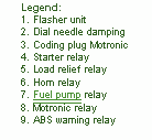
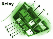
Fuse Panel Layout Diagram Parts: flasher unit, dial needle damping, coding plug motronic, starter relay, load relief relay, horn relay, fuel pump relay, motronic relay, ABS warning system.

Explanation Fuse Box Chevy s10 2001 Diagram

Fuse Box Chevy s10 2001 Diagram - This show you about Fuse Box Chevy s10 2001 Diagram.

Fuse Box Chevy s10 2001 Diagram


Fuse
Fuse

Fuse Panel Layout Diagram Parts: back up lamp, supply voltage, trailer rear, stop lamp supply, back lamp supply, park lamps supply voltage, trailer CHMSL supply voltage, fuel pump supply, ignition voltage.

Monday, September 15, 2014

Mercedes Explanation Fuse Box Year Benz 1995 C280 Diagram

Fuse Box Mercedes Benz 1995 C280 Diagram - Below is Fuse Box Mercedes Benz 1995 C280 Diagram.

Fuse Box Mercedes Benz 1995 C280 Diagram


Fuse
Fuse

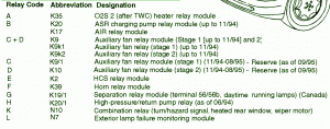
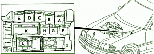
Fuse Panel Layout Diagram Parts: heater relay module, ASR charging pump relay module, A/R relay module, auxiliary relay fan module, HCS realay module, horn relay module, daytime running lamp, return pump relay, combination relay, hazard signal, heated rear window, wiper motor, exterior lamp failure monitoring module.

Sunday, September 14, 2014

Explanation Fuse Box Chevrolet ZR2 2003 Diagram

Fuse Box Chevrolet ZR2 2003 Diagram - This show you about Fuse Box Chevrolet ZR2 2003 Diagram.

Fuse Box Chevrolet ZR2 2003 Diagram


Fuse
Fuse

Fuse Panel Layout Diagram Parts: cigar lighter, data link connector, body control module, cruise control module, multifunction switch, driver front passenger, instrument panel cluster, view mirror switch, door lock, side window lock out switch, audio control, IP ashtray lamp, redundant steering wheel control, headlamp switch, seat lumbar switch,

Sunday, August 24, 2014

Build a Funk Twang Guitar Effect Box Wiring diagram Schematic

How to Build a Funk (Twang) Guitar Effect Box Circuit Diagram. This is an audio effect schema that give extra oscillation to your guitar, percussive, or semi percussive instruments, you can call it a funk box. This  guitar effect schema is basically a damped oscillator that is set slightly below its critical oscillation point.  

The oscillator part is constructed by feeding back the output signal through a bandpass schema, with the center frequency is adjusted by potentiometer R7 to add an extra “twang” , adjustable from low to high pitched timbre. Potentiometer R4 is used to adjust the gain of the oscillator, should be set to damp the oscillation at the desired decay time.  

To adjust it, turn the knob slowly until a steady oscillation occurs, and turn back slightly just before it happens (the oscillation should ceases slowly). Here is the schematic diagram of the schema.

Funk (Twang) Guitar Effect Box Circuit Diagram

Funk