Showing posts with label electronic. Show all posts

Thursday, November 13, 2014

Alternating on off switch electronic project circuit with explanation


A very simple alternating on off switch electronic circuit project can be designed using an 4096 CMOS hex inverter and some common electronic parts.
IC1is a regular Hex-inverter type and is constructed with MOS P-channel and N-channel enhancement mode devices in a single monolithic structure.
First push from this alternating on off switch activates the relay and another push de-activates the relay.

The type for D1 in not critical, even a 1N4148 will work.
Q1 transistor is an 2N4401 type , but can be replaced with some other type like : N100, NTE123A, 2N3904, 2N2222, 2N4013, etc.
For C2, if you find the relay acts not fast enough, you can change it to a lower value or use a ceramic cap of around 0.1μF.
The circuit can be powered from a 9 or 12 volts DC power supply circuit .

Unused input pins must be connected to an appropriate logic level and unused output pins must be left open.
Relay used in this project is an 6 volts relay type . R4 and LED1 are optional and can be removed from the circuit .

Monday, September 8, 2014

Temperature Monitor for Electronic Equipment

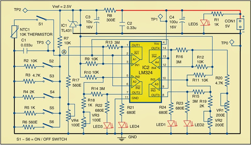
Build a Temperature Monitor for Electronic Equipment schema diagram. As most electronics components’ characteristics vary with temperature, they are selected as per expected operating temperature range of the equipment. So it is important that the equipment stays within the temperature range for which it is designed.


This schema warns when the temperature reaches predefined danger levels. Here the predefined levels are set to 45°C, 65°C, 85°C and 105°C, but one can set any other temperature levels to suit the equipment in use.Circuit and workingFig. 1 shows the temperature monitoring schema. It is built around 10k NTC thermistor NTC1, shunt regulator TL431 (IC1), popular comparator LM324 (IC2) and some other components.

 Temperature Monitor for Electronic Equipment Circuit Diagram

 temperature monitor for electronic equipment


IC2 activates corresponding LEDs (LED1 through LED4) when the temperature of thermistor NTC1 reaches the predefined level (refer Table I). The temperature is sensed by NTC1 and the produced corresponding voltage at point ‘A’ is fed to inverting terminal of all the four op-amps (A1 through A4). Switch S1 should be closed for this operation. This voltage level is compared with the reference voltage at non-inverting terminals of each op-amp. The reference voltage is obtained by voltage dividers from 2.5V reference source, which is produced using shunt regulator IC1. The reference voltage for each comparator can be set using presets VR1 through VR4.

http://streampowers.blogspot.com/2014/02/temperature-monitor-for-electronic.html

http://streampowers.blogspot.com/2014/02/temperature-monitor-for-electronic.html


The switches S2 through S6, together with resistors R2 through R6, are used for calibration purpose. For example, op-amp A4 of IC2 compares the voltage levels at point A (changing with change in temperature) with the reference voltage at its pin 12. The voltage level at pin 12 of A4 is adjusted with preset VR1. Switches S2 through S6 are used to simulate voltage levels corresponding to different temperatures.A4 is tuned for 45°C by keeping switch S3 in closed position and trimming preset VR1 until LED1 glows. S1 should be open during calibration. The same procedure is repeated for comparator A3, A2 and A1 to tune them for 65°C, 85°C and 105°C. Table I shows the presets and LEDs corresponding to each temperature level. After calibration, open switches S2 through S6.


Sourced By : EFY Author: Petre Tzv. Petrov

Wednesday, September 3, 2014

Switching Power Supply Electronic


Description: 
The following schema shows about Self Switching Power Supply Electronic Circuit Diagram. This schema based on the 7805 IC. Features: variable output voltage, every 100-ohm increment, output varies from 3.7V to 8.7V, the output voltage increases by 1 volt. Component: Transformer, Switch, Diode, Resistor, Capacitor, Transistor, IC.

Tuesday, August 19, 2014

Electronic Light Switch Wiring diagram Schematic

This is a simple Electronic Light Switch Circuit Diagram.. The schema is a light switch who triggers when light drops on photo resistor. It is fairly simple in construction and can be used in a million applications. The photo resistor and the trimmer work as a voltage divider and also polarize the transistor TR1. TR1 triggers TR2 and TR2 drives the relay. Trimmer R7 is for adjusting the sensitivity of the schema. 

 Switching Improves Regulator Efficiency Circuit Diagram

  Electronic Light Switch Circuit Diagram


Parts: 
R = photoresistor
R1= 4.7 Kohm
R2= 1.2 Kohm
R3= 2.2 Kohm
R4= 1.2 Kohm
R5= 1.2 Kohm
R6= 2.7 Kohm
R7= 100Kohm
Trimmer
C1 = 10uf/16V
electrolytic
TR1= BC107 - BC108 NPN
TR2= BC107 - BC108 NPN
TR3= BC557 - BC558 PNP - BC327
D1 = 1N4148 Relay = any 12Volt relay