On this page, I will introduce the room temperature controller with PIC. This equipment uses two temperature sensors, drives external equipment, and keeps the temperature of the room at preset temperature. The purpose of this equipment is for preventing room temperature going up with the heat of the computers. Electric cost will become high if an air-conditioner is always operated. Then, I made the equipment which adjusts the temperature of the room automatically using some ventilation fans. The function below preset temperature is a function attached moreover. I think that it can use for temperature control, such as a greenhouse.
Showing posts with label temperature. Show all posts
Showing posts with label temperature. Show all posts
Saturday, October 25, 2014
PIC16F873 Room temperature controller
Wednesday, October 15, 2014
Temperature Sensor Circuit Diagram
The LM35 temperature sensor provides an output of 10 mV/C for every degree Celsius over 0C. At 20C the output voltage is 20 10 = 200 mV. The circuit consumes 00. The load resistance should not be less than 5 kQ. A 4- to 20-V supply can be used.
Temperature Sensor Circuit Diagram

Monday, September 8, 2014
Temperature Monitor for Electronic Equipment
Build a Temperature Monitor for Electronic Equipment schema diagram. As most electronics components’ characteristics vary with temperature, they are selected as per expected operating temperature range of the equipment. So it is important that the equipment stays within the temperature range for which it is designed.

This schema warns when the temperature reaches predefined danger levels. Here the predefined levels are set to 45°C, 65°C, 85°C and 105°C, but one can set any other temperature levels to suit the equipment in use.Circuit and workingFig. 1 shows the temperature monitoring schema. It is built around 10k NTC thermistor NTC1, shunt regulator TL431 (IC1), popular comparator LM324 (IC2) and some other components.
Temperature Monitor for Electronic Equipment Circuit Diagram
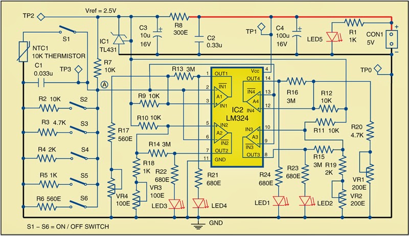
IC2 activates corresponding LEDs (LED1 through LED4) when the temperature of thermistor NTC1 reaches the predefined level (refer Table I). The temperature is sensed by NTC1 and the produced corresponding voltage at point ‘A’ is fed to inverting terminal of all the four op-amps (A1 through A4). Switch S1 should be closed for this operation. This voltage level is compared with the reference voltage at non-inverting terminals of each op-amp. The reference voltage is obtained by voltage dividers from 2.5V reference source, which is produced using shunt regulator IC1. The reference voltage for each comparator can be set using presets VR1 through VR4.


The switches S2 through S6, together with resistors R2 through R6, are used for calibration purpose. For example, op-amp A4 of IC2 compares the voltage levels at point A (changing with change in temperature) with the reference voltage at its pin 12. The voltage level at pin 12 of A4 is adjusted with preset VR1. Switches S2 through S6 are used to simulate voltage levels corresponding to different temperatures.A4 is tuned for 45°C by keeping switch S3 in closed position and trimming preset VR1 until LED1 glows. S1 should be open during calibration. The same procedure is repeated for comparator A3, A2 and A1 to tune them for 65°C, 85°C and 105°C. Table I shows the presets and LEDs corresponding to each temperature level. After calibration, open switches S2 through S6.
Sourced By : EFY Author: Petre Tzv. Petrov
Monday, August 18, 2014
Simple Temperature Sensor Arduino
Hello people, it’s been a while since I have posted projects on this website. This semester was really busy, I didn’t have time to much else, but soon I will have my winter holiday (Here in south our summer holiday is from December to February).
Today I am going to show you how to build a simple temperature sensor using one LM35 Precision Temperature Sensor and Arduino, so you can hookup on your future projects. The schema will send serial information about the temperature so you can use on your computer, change the code as you will. I’m planning to build a temperature sensor with max/min + clock + LCD, and when I get it done, I will post here.
Parts:
- Arduino (You can use other microcontroller, but then you will need to change the code).
- LM35 Precision Centigrade Temperature Sensor, you can get from any electronic store. Here is the DATA SHEET.
- BreadBoard
This is a quick and simple step. Just connect the 5V output from arduino to the 1st pin of the sensor, ground the 3rd pin and the 2nd one, you connect to the 0 Analog Input.
Down goes some pictures that may help you, click to enlarge:


Here is the Arduino Code, just upload it and check the Serial Communication Option.
You can also download the .pde HERE.
/*
An open-source LM35DZ Temperature Sensor for Arduino. This project will be enhanced on a regular basis
(cc) by Daniel Spillere Andrade , http://www.danielandrade.net
http://creativecommons.org/license/cc-gpl
*/
int pin = 0; // analog pin
int tempc = 0,tempf=0; // temperature variables
int samples[8]; // variables to make a better precision
int maxi = -100,mini = 100; // to start max/min temperature
int i;
void setup()
{
Serial.begin(9600); // start serial communication
}
void loop()
{
for(i = 0;i< =7;i++){ // gets 8 samples of temperature
samples[i] = ( 5.0 * analogRead(pin) * 100.0) / 1024.0;
tempc = tempc + samples[i];
delay(1000);
}
tempc = tempc/8.0; // better precision
tempf = (tempc * 9)/ 5 + 32; // converts to fahrenheit
if(tempc > maxi) {maxi = tempc;} // set max temperature
if(tempc < mini) {mini = tempc;} // set min temperature
Serial.print(tempc,DEC);
Serial.print(" Celsius, ");
Serial.print(tempf,DEC);
Serial.print(" fahrenheit -> ");
Serial.print(maxi,DEC);
Serial.print(" Max, ");
Serial.print(mini,DEC);
Serial.println(" Min");
tempc = 0;
delay(1000); // delay before loop
}
An open-source LM35DZ Temperature Sensor for Arduino. This project will be enhanced on a regular basis
(cc) by Daniel Spillere Andrade , http://www.danielandrade.net
http://creativecommons.org/license/cc-gpl
*/
int pin = 0; // analog pin
int tempc = 0,tempf=0; // temperature variables
int samples[8]; // variables to make a better precision
int maxi = -100,mini = 100; // to start max/min temperature
int i;
void setup()
{
Serial.begin(9600); // start serial communication
}
void loop()
{
for(i = 0;i< =7;i++){ // gets 8 samples of temperature
samples[i] = ( 5.0 * analogRead(pin) * 100.0) / 1024.0;
tempc = tempc + samples[i];
delay(1000);
}
tempc = tempc/8.0; // better precision
tempf = (tempc * 9)/ 5 + 32; // converts to fahrenheit
if(tempc > maxi) {maxi = tempc;} // set max temperature
if(tempc < mini) {mini = tempc;} // set min temperature
Serial.print(tempc,DEC);
Serial.print(" Celsius, ");
Serial.print(tempf,DEC);
Serial.print(" fahrenheit -> ");
Serial.print(maxi,DEC);
Serial.print(" Max, ");
Serial.print(mini,DEC);
Serial.println(" Min");
tempc = 0;
delay(1000); // delay before loop
}
Anything just ask!
Source by : link


